refrigerationcycle Real Refrigeration
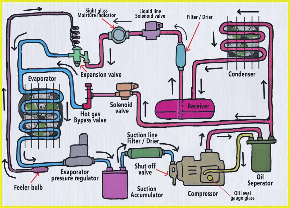
This is how the refrigeration cycle diagram looks: Yeah, it seems complicated at first, but it will be easier to understand once I have explained the refrigeration cycle diagram section by section. It important to understand the basic refrigeration cycle, to comprehend what is going on within the air conditioner units, we cannot see it.
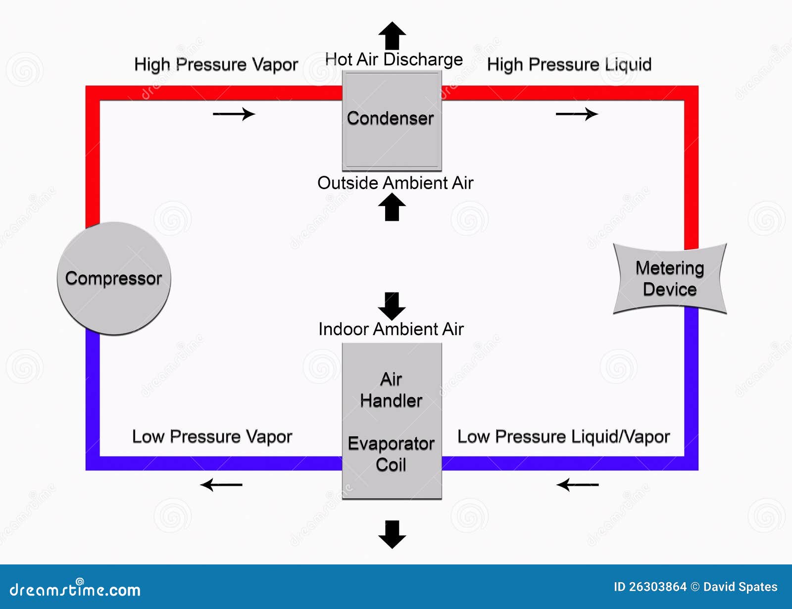
Basic Refrigeration Cycle stock illustration. Illustration of handler 26303864
Refrigeration Cycle Diagram Explained Home » Refrigeration » Refrigeration Cycle Diagram Explained The thermodynamic processes in the refrigeration cycle are complex. Calculation using formulae and tables requires a considerable amount of effort due to the three different states of the refrigerant from liquid, boiling and gaseous.

The Refrigeration Cycle In easy to understand descriptions & diagrams!
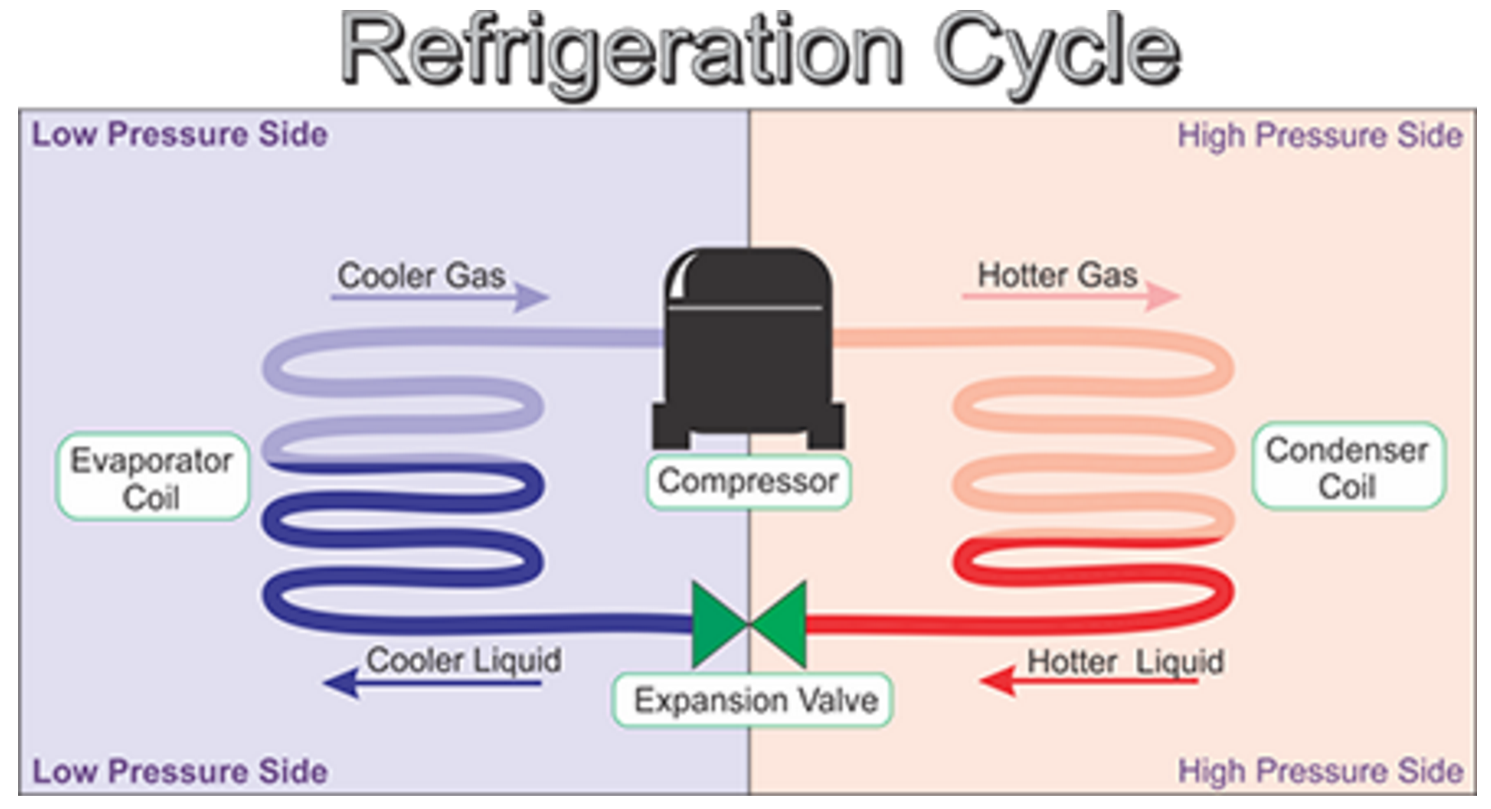
Refrigeration Cycle Heat flows in direction of decreasing temperature, i.e., from high-temperature to low temperature regions. The transfer of heat from a low-temperature to high-temperature requires a refrigerator and/or heat pump. Refrigerators and heat pumps are essentially the same device; they only differ in their objectives.
CHILLER CHOONG The Basic Refrigeration Cycle
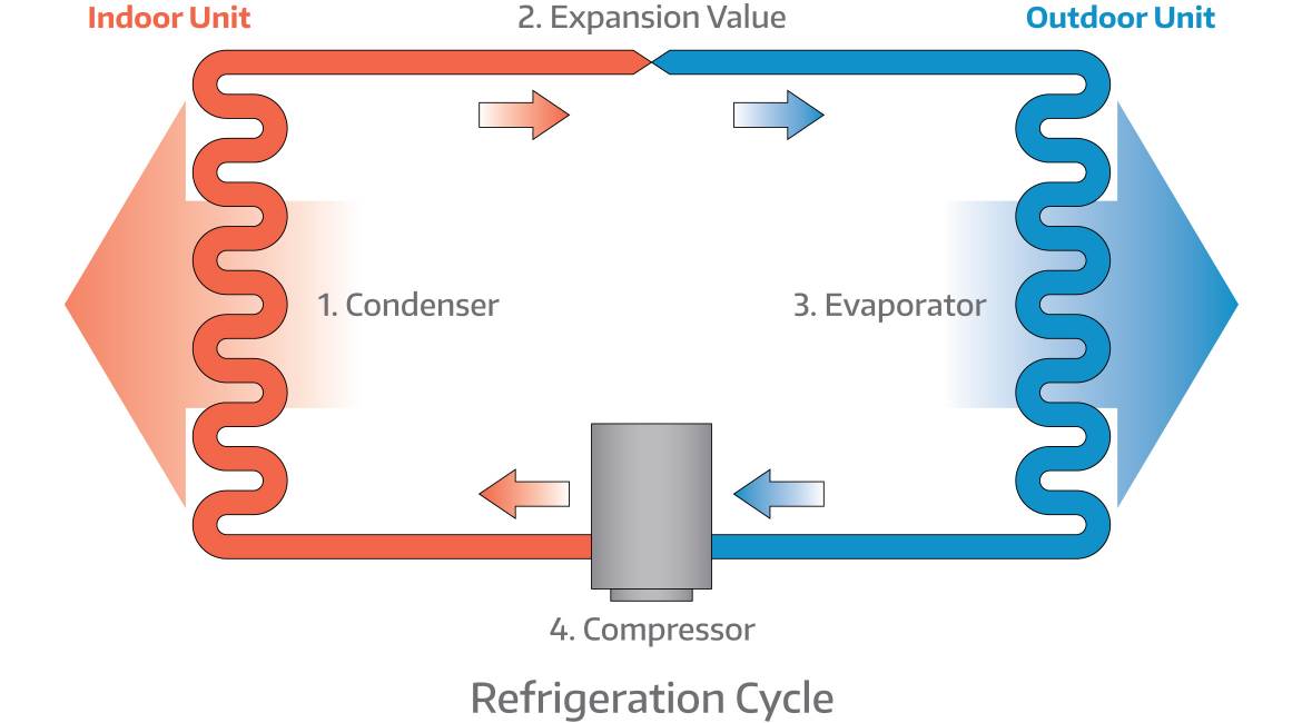
For comparison, a simple stylized diagram of a heat pump's vapor-compression refrigeration cycle: 1) condenser, 2) expansion valve, 3) evaporator, 4) compressor (Note that this diagram is flipped vertically and horizontally compared to the previous one) [6] Temperature-entropy diagram of the vapor-compression cycle.

HVAC The Refrigeration Cycle HVAC Beginners
The refrigeration cycles can also be represented in a P-H diagram. Figure 5: P-H diagram representation of a dry refrigeration cycle Refrigerant fluid choice: We now turn our attention to the fluids. Usually, one tends to pick pL as low as possible, but not below atmospheric pressure.
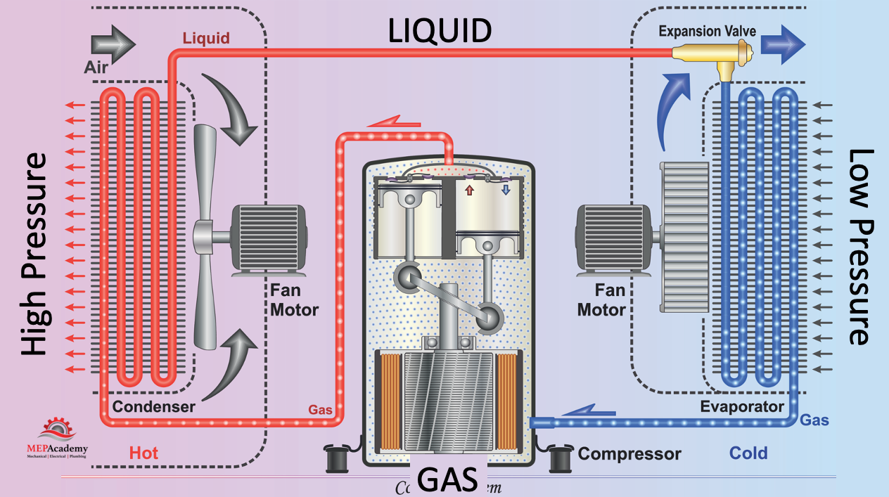
Refrigeration Cycle 101 MEP Academy
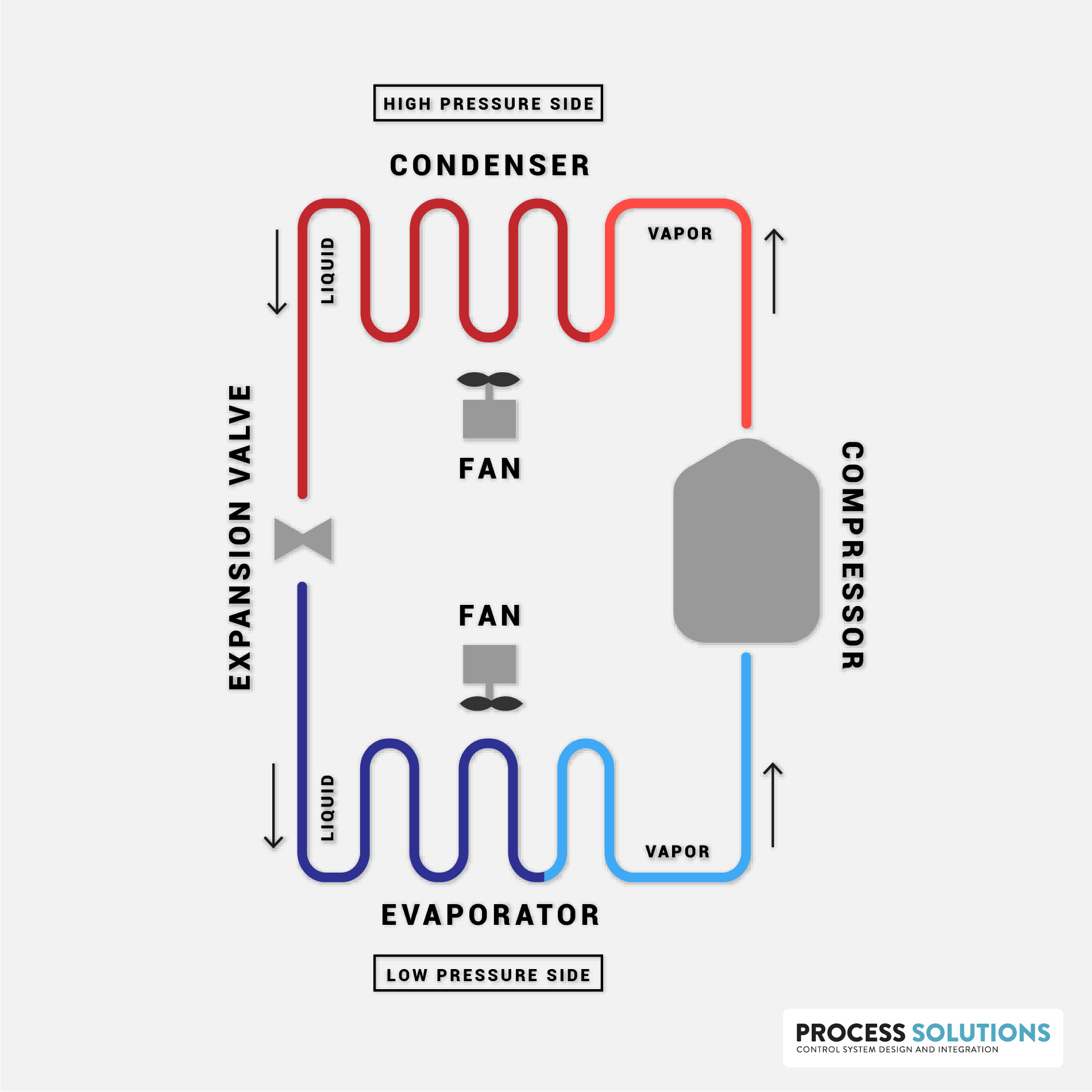
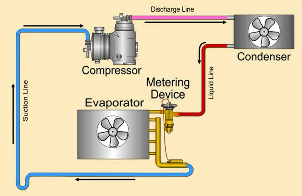
We'll discuss the refrigeration cycle using this cycle diagram. Feel free to copy this refrigeration cycle diagram and print it out. Component #1 is the compressor. It takes refrigerant vapor in from the low pressure side of the circuit, and discharges it at a much higher pressure into the high pressure side of the circuit.
The 4 Main Important Components of Refrigeration Cycle
The following figure indicates the refrigeration cycle schematic with the above-mentioned processes, which can be also represented in the log (p)-h diagram, as shown in figure 1. These thermodynamic processes form a closed cycle called the theoretical Linde circuit, which is standard circuit for real compressor refrigeration systems.
Knowledge — Refrigeration Cycle. The refrigeration cycle is a critical… by Ravti Ravti
August 1, 2023 When troubleshooting a refrigeration system, it is important to understand how the refrigeration cycle accomplishes the goal of removing heat from a room and rejecting the heat absorbed by the refrigerant to the outdoor ambient space. The entire process is actually quite simple.
How Does a Compression Refrigeration System Work? Process Solutions, Inc.
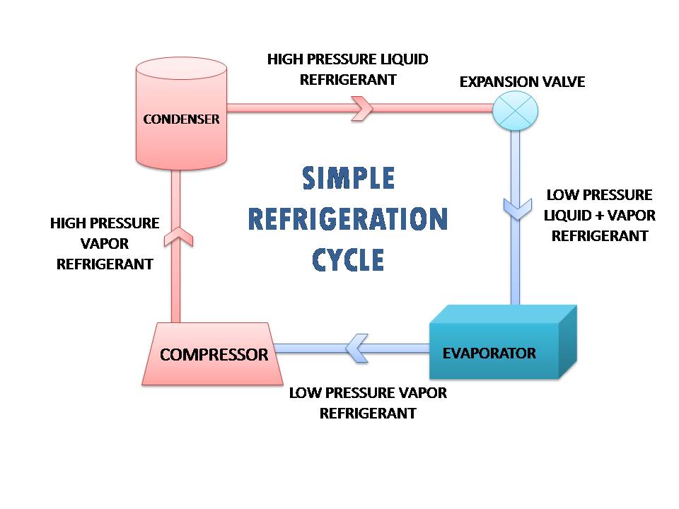
The refrigeration cycle is a thermodynamic cycle that generates refrigerating effects with the use of mainly an evaporator, compressor, condenser & expansion valve.
HVAC system acting up? Take a look at its superheat measurements HVAC BRAIN
Fig. 1 shows schematic diagram of simple Vapour Compression Refrigeration System running on Vapour Compression Cycle (V.C.C.). Vapour compression refrigeration system consists of four principal elements. They are Compressor, Condenser, Expansion Valve and Evaporator.
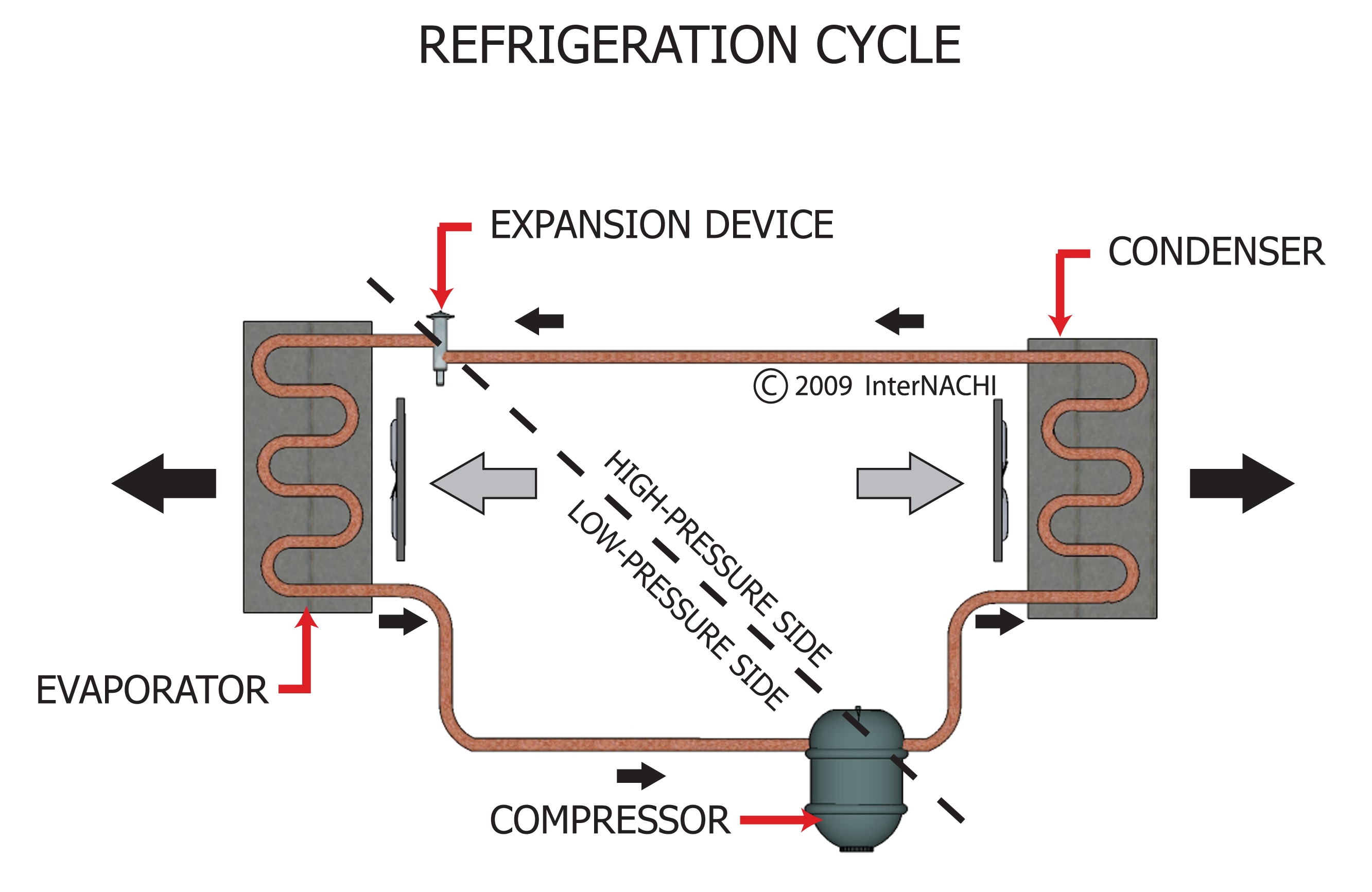
Refrigeration Cycle Inspection Gallery InterNACHI®
1. The Compressor. The Compressor can be thought of as the heart of the process. It acts like a pump to create the circulation by compressing the refrigerant gas, creating a pressure difference that drives the refrigerant around the circuit in a continuous cycle. 2. The Condenser.
How can i design a refrigeration cycle ? AskEngineers
Shown below are the cyclic refrigeration device operating between two constant temperature reservoirs and the T-s diagram for the working fluid when the reversed Carnot cycle is used. Recall that in the Carnot cycle heat transfers take place at constant temperature. If our interest is the cooling load, the cycle is called the Carnot refrigerator.
15 Major Components and Controls of Refrigeration System Refcon hvac
Refrigeration Cycle Diagram Compression The cycle begins with the compressor, which is essentially a pump driven by an electric motor. The compressor's primary function is to compress the refrigerant gas, increasing its temperature and pressure. Heat Dissipation
Mechanical Info World Ideal Basic Refrigeration cycle
In this HVAC Video, I give a Tutorial to Explain the Refrigeration Cycle with Superheat and Subcooling Step by Step, Detailed and Concise! I go over how the.
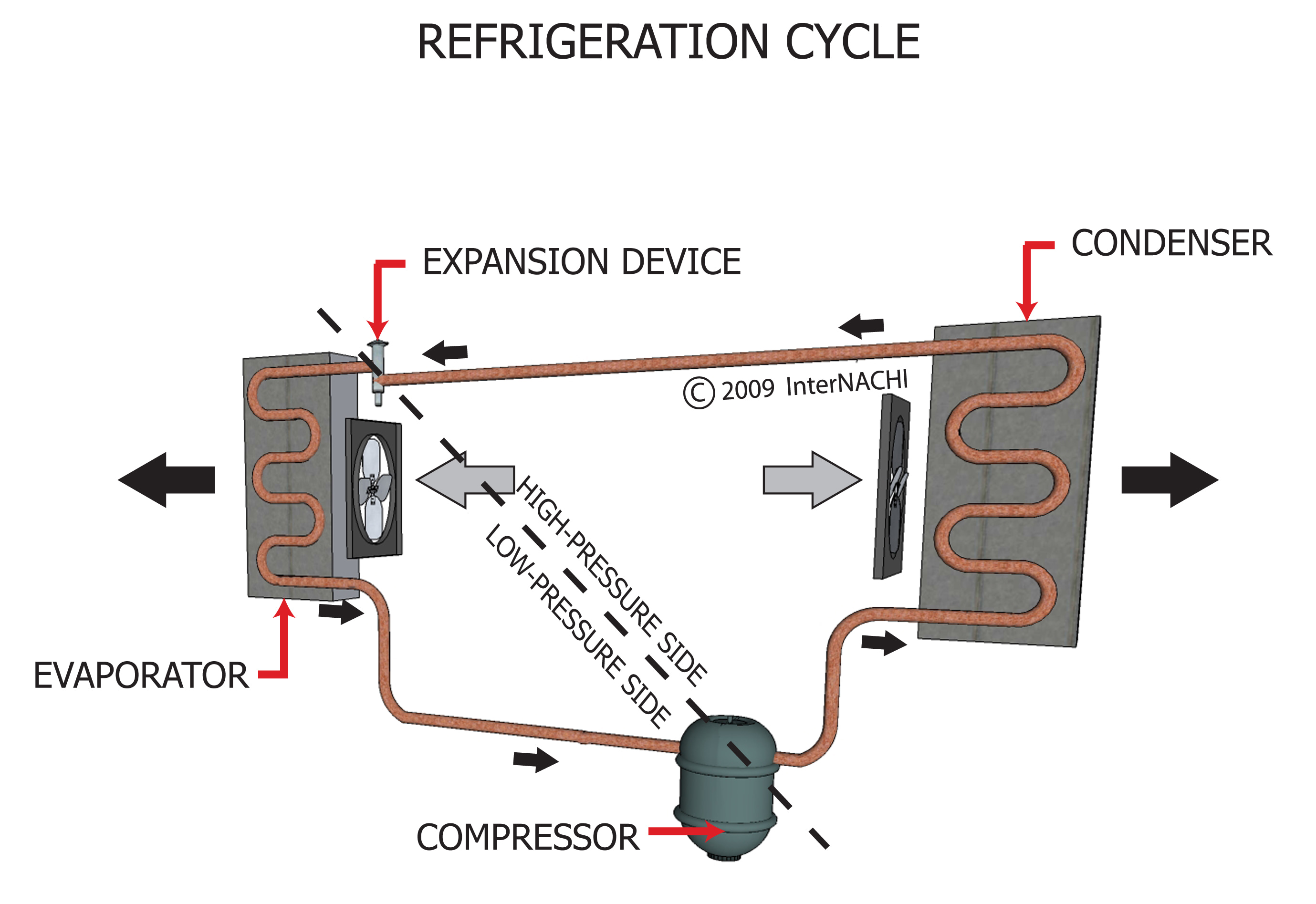
Refrigeration Cycle Inspection Gallery InterNACHI®
Number of views: 98723 A refrigerator is a device which is designed to remove heat from a space that is at lower temperature than its surroundings. The same device can be used to heat a volume that is at higher temperature than the surroundings. In this case the device is called a Heat Pump.
Should Water Be Used as a Refrigerant? Owlcation
Table of Contents What is a Refrigeration? What is Refrigeration Cycle? Refrigeration Cycle Working Types of Refrigeration Cycles 1) Vapour Compression Cycle 2) Vapour Absorption Cycle 3) Gas Cycle 4) Stirling Cycle 5) Reverse Carnot Cycle Components of Refrigeration System Advantages and Disadvantages of Refrigeration System
